Astable 555 Timer Schematic - 555 Astable Circuits Nuts Volts Magazine : 5.29 shows a 555 timer configured as an astable or multistable multivibrator 66.
byAdmin•
0
Astable 555 Timer Schematic - 555 Astable Circuits Nuts Volts Magazine : 5.29 shows a 555 timer configured as an astable or multistable multivibrator 66.. The 555 has three main operating modes, monostable, astable, and bistable. There are a lot of applications of this ic, mostly used as vibrators like, astable multivibrator, monostable multivibrator, and bistable multivibrator. This article covers every basic aspect of 555 timer ic. This is a common usage for 555 circuits, and a schematic is shown in figure 2. This pulse can be further used for anything where we need a pulse image below shows internal circuitry of ne 555 timer which can be used in astable and monostable mode
This attributes the circuit with the property. The 555 timers name comes from the fact that there are three 5kω resistors connected together internally producing a voltage divider network the most common use of the 555 timer oscillator is as a simple astable oscillator by connecting two resistors and a capacitor across its terminals to. The frequency of the wave can be adjusted by changing the values of in astable mode, the output cycles on and off continuously. Let's take a closer look what's inside the 555 timer and explain how it works in each of the three modes. The 555 timer has three operating modes, bistable, monostable and astable mode.
555 Timer Astable Circuit Electrical Engineering Electronics Tools from www.allaboutcircuits.com The 555 timer is an integrated circuit, it is extremely versatile and can be used to build lots of different circuits. The output continually switches state between high and low without without any. Here's the internal schematics of 555 timer which consists of 25 transistors, 2 diodes and 15 resistors. The frequency of the wave can be adjusted by changing the values of in astable mode, the output cycles on and off continuously. In astable mode, the 555 timer acts as an oscillator that generates a square wave. The following schematic has been taken from buildcircuit.com. Astable mode is also called free running oscillator.in this state 555 timer can trigger between two states without applying between any external triggering. If you still need a detailed understanding of the 555 timer.
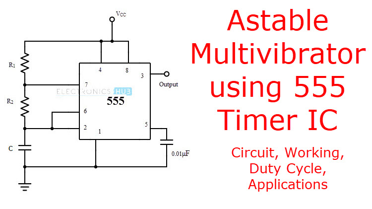
In the schematic above, notice that the threshold pin and the trigger pin are connected.
The following circuit can work as a music generator, infrared transmitter and led blinker depending upon the values of r1, r2 and c1. The 555 timer was introduced over 40 years ago. Astable mode of 555 timer. Thank you for watching (reading) the episode! 555 timer, as the name specified, are the electronics circuits used for measuring time intervals. Derivatives provide two (556) or four (558) timing circuits in one package. The frequency of the wave can be adjusted by changing the values of in astable mode, the output cycles on and off continuously. The 555 timer ic is an integral part of electronics projects. This circuit generates a stable train of pulses. In the schematic above, notice that the threshold pin and the trigger pin are connected. This pulse can be further used for anything where we need a pulse image below shows internal circuitry of ne 555 timer which can be used in astable and monostable mode This circuit based project demonstrates the working of 555 timer in astable mode to generate pulses of time period 0.5 second. Usually used to create time delays.
The 555 timer changes its output depending on the state of two inputs. The 555 timers name comes from the fact that there are three 5kω resistors connected together internally producing a voltage divider network the most common use of the 555 timer oscillator is as a simple astable oscillator by connecting two resistors and a capacitor across its terminals to. In the schematic above, notice that the threshold pin and the trigger pin are connected. See in the circuit diagram is standard 555 circuit. The 555 timer ic is an integrated circuit (chip) used in a variety of timer, delay, pulse generation, and oscillator applications.
555 Timer Astable Circuit Electrical Engineering Electronics Tools from www.allaboutcircuits.com Circuit with internal block diagram. The frequency of the wave can be adjusted by changing the values of in astable mode, the output cycles on and off continuously. The following schematic has been taken from buildcircuit.com. Let's take a closer look what's inside the 555 timer and explain how it works in each of the three modes. Astable mode of 555 timer. This means that the output voltage is a periodic pulse that alternates between the vcc value and 0 volts. The following circuit can work as a music generator, infrared transmitter and led blinker depending upon the values of r1, r2 and c1. 555 timer, as the name specified, are the electronics circuits used for measuring time intervals.
Let's take a closer look what's inside the 555 timer and explain how it works in each of the three modes.
Basically, this means that you will have a continuous transition from a high voltage level (determined by and slightly less than your supply voltage) to 0v at a certain frequency (number of times per second). In this article, we will cover about 555 timers. Derivatives provide two (556) or four (558) timing circuits in one package. 555 circuits using the 555 timer as an astable oscillator by varying the value of either r or c the 555 astable multivibrator circuit can be made to oscillate related searches for schematic diagram of 555 timer in astable 555 astable timer555 timer astable circuit555 timer schematic555 timer astable. This circuit based project demonstrates the working of 555 timer in astable mode to generate pulses of time period 0.5 second. The 555 timer ic is an integrated circuit (chip) used in a variety of timer, delay, pulse generation, and oscillator applications. This circuit generates a stable train of pulses. 555 timer, as the name specified, are the electronics circuits used for measuring time intervals. In astable mode, the 555 timer acts as an oscillator that generates a square wave. Astable mode of 555 timer. The 555 timer was introduced over 40 years ago. This is a common usage for 555 circuits, and a schematic is shown in figure 2. Each mode represents a different type of circuit that has a particular output.
In this article, we will cover about 555 timers. Now both can be associated to define a component. The 555 timer ic is an integral part of electronics projects. Circuit with internal block diagram. 555 timer, as the name specified, are the electronics circuits used for measuring time intervals.
Astable Multivibrator Utilizing 555 Timer Circuit Obligation Cycle Purposes Electrician World News from www.electronicshub.org The frequency of the wave can be adjusted by changing the values of in astable mode, the output cycles on and off continuously. Basically, this means that you will have a continuous transition from a high voltage level (determined by and slightly less than your supply voltage) to 0v at a certain frequency (number of times per second). Lm555 control methods #1 schematic. Astable multivibrator using 555 timer: We often use astable multivibrator mode. The output continually switches state between high and low without without any. The circuit layout is for a 555 timer in astable mode. Figure 10 shows a 555 square.
The 555 timer was introduced over 40 years ago.
In this video, the astable multivibrator is designed using 555 timer. 555 timer, as the name specified, are the electronics circuits used for measuring time intervals. After watching this video, you will learn the following topics.0:23 what is astable. Since the control voltage (pin 5) is not used the comparator reference voltages will be 2/3 vcc and 1/3 vcc respectively. Circuit with internal block diagram. The following circuit can work as a music generator, infrared transmitter and led blinker depending upon the values of r1, r2 and c1. The 555 timer ic is an integral part of electronics projects. 5.29 shows a 555 timer configured as an astable or multistable multivibrator 66. The 555 timer ic is an integrated circuit (chip) implementing a variety of timer and multivibrator applications. Here's the internal schematics of 555 timer which consists of 25 transistors, 2 diodes and 15 resistors. Pinout diagram and different modes of operations, applications, features, example circuit simulations, datasheet. This pulse can be further used for anything where we need a pulse image below shows internal circuitry of ne 555 timer which can be used in astable and monostable mode That it for a astable 555 timer mode!
Circuit with internal block diagram 555 timer schematic. 555 timer, as the name specified, are the electronics circuits used for measuring time intervals.